Version 5.14.9 - November 2024

This calculation tool will give recommendations to configure a CASM, EMA or LEMC high performance actuators, based on the application data.
Starting from the user requirements and operating conditions, it will present combinations of linear unit, motor adapter and motor that fulfil them, showing the combination maximum performances versus the requirements and the theoretical lifetime achievable. It’s also possible to select the desired accessories and save a pdf report with the application data, performance requirements and the selected product configuration.


Upload motion profile for CASM, EMA & LEMC

Application data

System of measurement:
Select version:

Basic: simple calculation considering only a constant force acting on the actuator and acceleration and deceleration values defined as speed * 2. It does not include payload mass, friction and external forces

Advanced: detailed calculation using all relevant input parameters

Direction of movement:

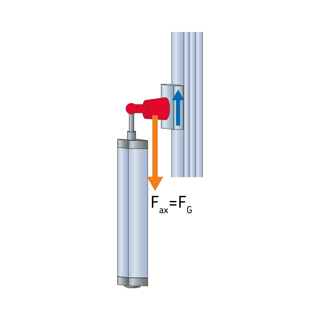
Vertical push
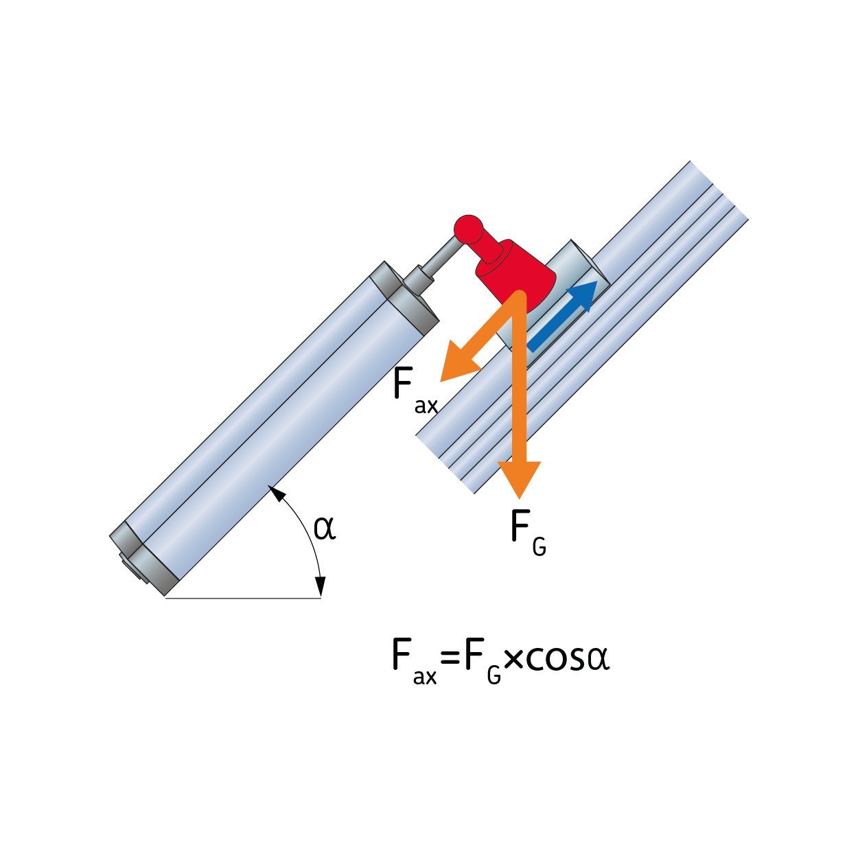
Diagonal push
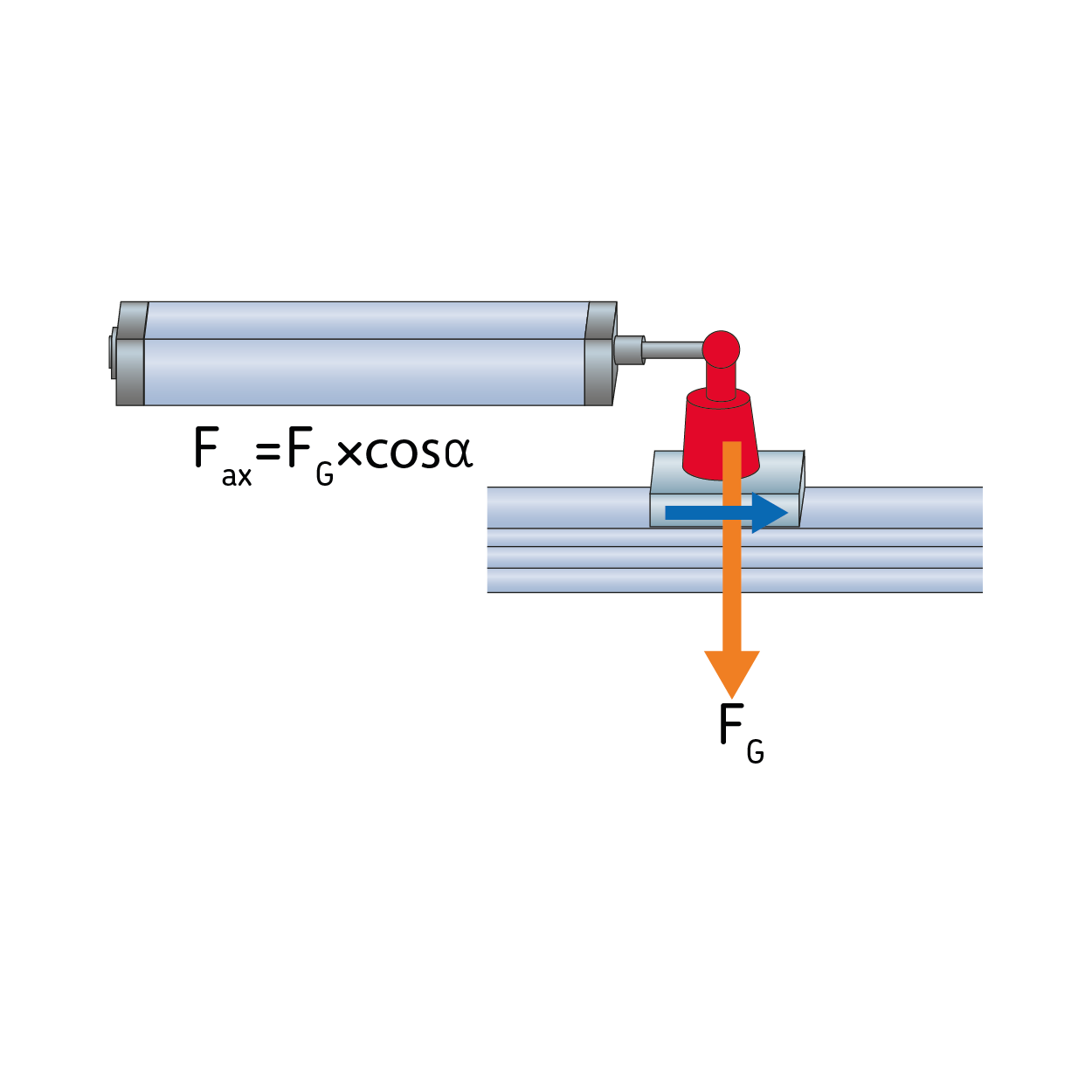
Horizontal
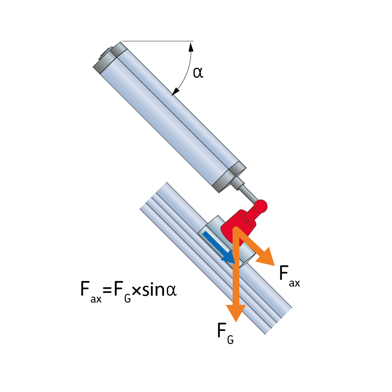
Diagonal pull
Vertical pull

Diagonal angle needs to be between 0.0 and 90.0

Friction:

Friction coefficient must be between 0.0 and 10.0

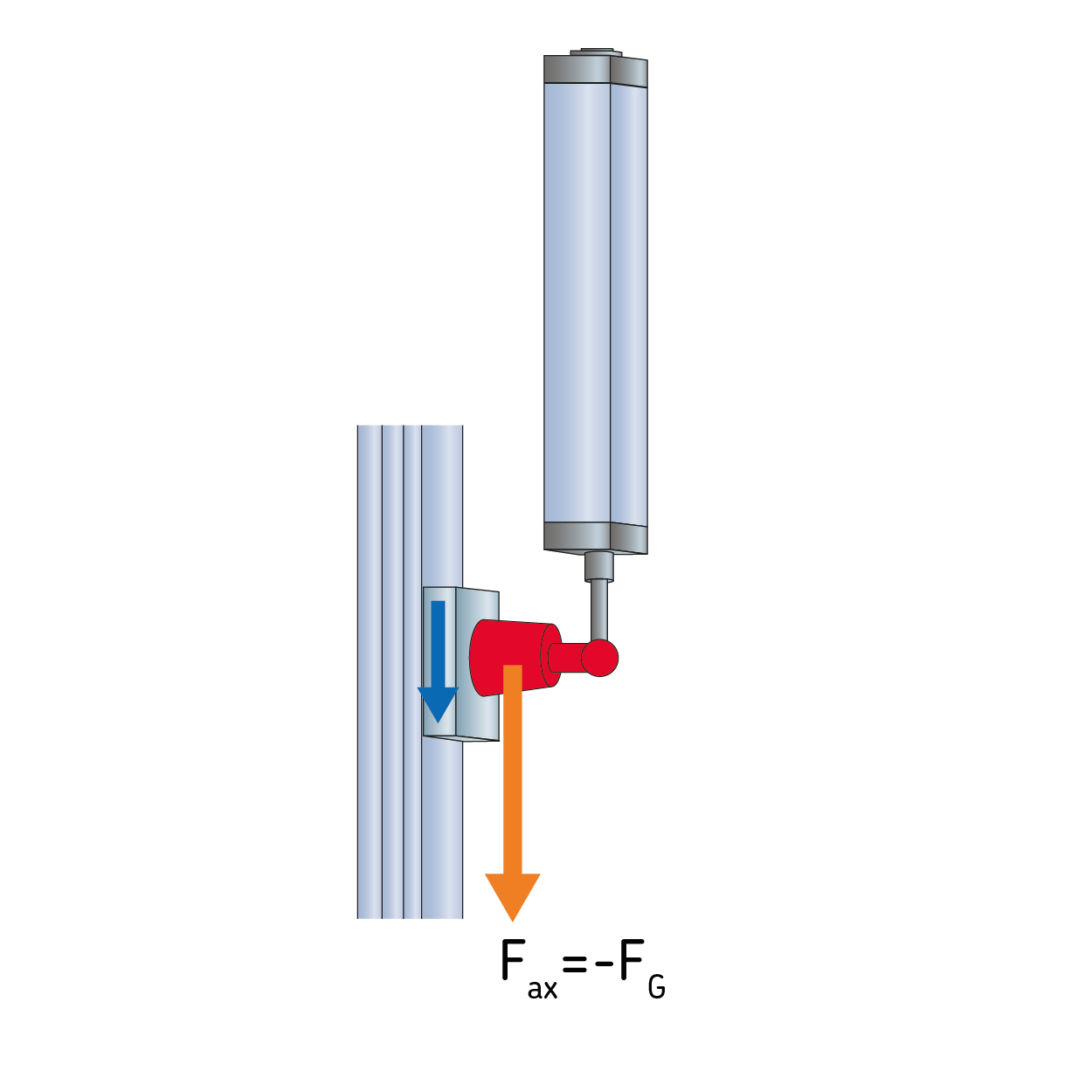
With Friction it is possible to define an overall friction force between a moving mass and a sliding surface. The friction force is based on the gravity force FG due to the specified mass in section Motion Profile and the angle α (see direction of movement). The friction coefficient is the relation between the normal force FN and the friction force FR The friction coefficient between two steel plates can be set to 0.1.


Motion profile


Input table for motion profile:

Mouseover the parameter name to get more information.

Move to position Relative distance Moving mass Constant force Mean force Speed Acceleration Deceleration Moving time Pause time Cycle step time
1  
2
Position needs to be between 0 and 2000mm This step has no movement, delete it and try again Moving mass needs to be in the range 0 to 100000kg Force needs to be in the range 0 to 60000N Constant force needs to be between 0 and 60000N Pause time needs to be in the range 0 to 300s Max speed needs to be between 0.0005m/s and 1.060m/s Max acceleration needs to be between 0m/s2 and 12.000m/s2 Max deceleration needs to be between 0m/s2 and 12.000m/s2

Motion profile diagrams:
Mouse over the points to get the actual values
Lifetime calculation

Motor selection

Motor brake option
Actuator configuration

Result list

This tool is used to calculate only high-performance actuators CASM and LEMC. For all the other Ewellix actuator, please use the “Product selection” section.

The highlighted solution is the best choice considering performance capacity vs usage.

The parameters you entered do not exactly match the specification of our products. The list below shows the closest results that partly fulfil the requirements. Please contact Ewellix to get a dedicated support.

Section size
[mm]
Section size
[in]
Linear Unit Screw type Screw size Required power
[kW]
Motor Gear Ratio Force capacity linear unit Speed capacity motor Motor torque capacity Rated motor power [W] Theoretical lifetime (L10) Theoretical lifetime (L10) capacity
n. cycles
  • Details

    System information

    Linear unit designation:

    Motor designation:

    Motor brand/type:

    Item Unit Application requirement Usage of capability System capability
    Linear unit
    Stroke:
    Mean force: N
    Peak force: N
    Mean linear speed:
    Max linear speed:
    Max acceleration:
    Max deceleration:
    Screw lead: N/A
    Linear unit inertia [seen from motor shaft]: N/A

    Boundary dimensions for 3rd party motor

    adapter
    mm (in)

    In case your selected 3rd party motor doesn't fit into these dimensions, please contact Ewellix for custom motor adapters

    Gearbox Insert your 3rd party motor parameters
    Max input torque:
    Max input speed:
    Gearbox inertia [seen from motor shaft]: N/A
    Gear Ratio - N/A
    Actuator configuration - N/A
    Motor inertia (including brake)
    Motor weight (including brake)
    Gear Ratio
    Motor Insert your 3rd party motor parameters
    Mean torque:
    The value does not meet the minimum requirements
    Peak torque:
    The value does not meet the minimum requirements
    Mean speed:
    The value does not meet the minimum requirements
    Maximum speed:
    The value does not meet the minimum requirements
    Motor inertia [seen from motor shaft]: N/A
    Motor inertia (including brake)
    Motor weight (including brake)
    Gear Ratio
    Actuator
    Total weight: -
    Total inertia [seen from motor shaft]: -
    Load inertia vs Motor inertia ratio: - -
  • Motor Torque vs RPM
    Mouse over the points to get the actual values
    Mouse over the points to get the actual values

Selected actuator with third-party motor

Section size
[mm]
Section size
[in]
Linear Unit Screw type Screw size Motor Gear Ratio Speed capacity motor Force capacity linear unit Motor torque capacity Theoretical lifetime (L10) Theoretical lifetime (L10) capacity
n. cycles

Following estimated nominal motor curve has been calculated

Mouse over the points to get the actual values

Options

Available options for:

Name Designation Description

Accessories

To filter the list of accessories by accessory location, click on the appropriate circle.

(Click here to see all accessories)

Mouseover the designation to see the accessory pictures.

* Required

Ordering information

Mouseover the designation to see the pictures.

Name Designation